RC Car Project
Mark I: Slipper
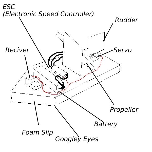
A sketch of slipper
For a while I had wanted to do some practical engineering, I was in A-level, just doing theory with nothing else to do. I wanted to learn engineering, to make things and gain actual experience. After browsing the internet, I found RC electronics. This was the perfect project for me, as the electronics were very simple yet effective and versatile, allowing me to focus on what I valued most: The design. I wanted to do mechanical engineering. Gears, belts and wheels. Not get into the nitty gritty of electronics. (Although I would also do electronic projects in the future, but that's a subject for a different page). So after purchasing some electronics off the internet, I decided to whip up something quick and easy. No 3D modelling or complex design. Just some cheap materials, creativity and duct tape. I wanted to get a feel for the components, to set them up correctly and to have a bit of fun. By my Dad's suggestion, I made a slip. A wedge of foam with a propeller and rudder. I made it in about an hour. And so, Slipper was born. Unfortunately I could not find the pictures and videos of slipper we took, however I do have a good memory of it. Pictured on the right is a simple diagram of Slipper. It's base was a wedge of foam, cut from a bit of packaging. Two pieces of thin balsa wood was used: One to hold the motor and propeller upright and one to serve as the rudder. The propeller was from an old drone, stuck to the motor with a bit of tape and glue. The rudder was attached to the servo with a length of wire, each end slid into the wood grain for an attachment point. The battery, ESC and receiver were slapped onto the front half, and all of it was secured with a mixture of string, duct tape and electrical tape.
Slipper immediately ran into some problems. Firstly: The friction between the carpet and foam was way too high, causing it to barely move. Next we tried a hardwood floor. This worked... but we could go faster. To reduce surface area, thus the friction, four googley eyes were stuck to the bottom. These were incredible, and at times it got so fast it was hard to control!
New ideas:
- Using an RC system
- Using propellers as a form of propulsion
- Using "skis" to allow for motion
Lessons learned:
- Propellers are difficult to control, and don't leave much room for manoeuvrability. Wheels will most likely be preferable
- RC system control and sensitivity: Doing this allowed me to get a feel for how an RC system handled, along with how to correctly set one up
- The servo worked but had a plastic connection and had low torque. A better one should be purchased for the next project
Mark II: Snark
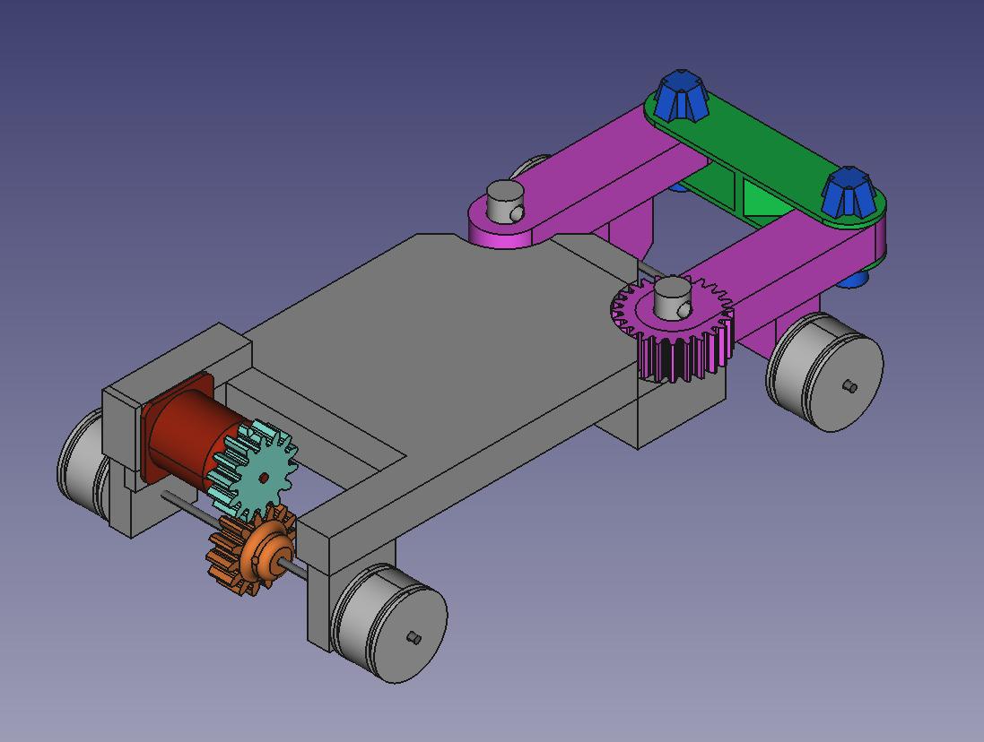
An early model of snark.
Tragically the original model is lost to time
After the initial success of Slipper, I decided to make a more engineered and advanced craft. So, with no education, practice or prior knowledge about practical design and some free CAD software I found online I forged ahead, ready to create. The method of making the main body was quite simple: Make a rectangular brick, and chisel out any places I needed to put stuff. Simple. At the rear of the Chassis a large cut was made, in this was inserted the motor, two gears and an axle. The front had two large pins that two arms sat on, secured by cotter pins. A bar connected these two with pin joints, allowing them to freely move. The right arm had a gear built into it that was connected to another gear in a 1:1 ratio. This second gear was connected to the servo. After testing, it was evident the servo needed a firmer connection to the car to actually turn the gear, so to fix this I designed and printed a housing for it. All axles were 3mm, and the wheels were 3D printed and secured to the axles with headless screws fitting into notches carved by a dremel. The wheels were made to fit LEGO tyres I had spare. The tyres held up really well under use conditions. The electronics were secured to the centre by electrical tape, and the motor was secured by bolts slotted through drilled holes in the chassis. The solid 3D printed chassis did provide several problems, such as the two pins that served as connections for the steering arms. One of them broke, which was an easy fix (drill a hole through the chassis and broken pin, bolt them together with a bolt and washer). This did show that 3D printed parts did have strength limitations, which limits how small 3D parts can get.
Snark
After showing it online, somebody mentioned the sound it made while steering sound similar to the Snark from half life. The name stuck.
New ideas:
- Using 3D printing
- Using gear systems to control wheels
- Double-Armed Steering system
- Using steel axles
- Using LEGO tyres
- Purchased a stronger servo
Lessons learned:
- ESC was incapable of reversing, a more advanced model was needed
- Steel axles held up well under the load conditions
- 3D printed parts held up well under the conditions, however the larger the part the harder it was to get a successful print, and the more it failed. 3D printed parts should be smaller in the future
- The servo required good attachment to the body to function
- The double-armed steering system performed well
- Gears worked really well, but a 1:1 ratio was a bit too fast
- The bolted joints used to attach the motor to the chassis and to repair the broken pin were amazingly effective and cheap
- The stronger servo worked well
Mark III: Headcrab
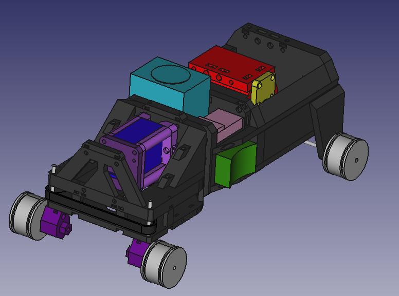
The 3D model of Headcrab,
also unfortunately lost to time
Headcrab
Headcrab is the next craft I made. It really pushed the boundaries of what I could design as well as introduce many new ideas of how to build an RC car. I designed from the front-backwards, starting with the steering and ending with the power transmission. The body is made of three compartments:
- Front (Steering)
- Middle (Electronics)
- Rear (Power)
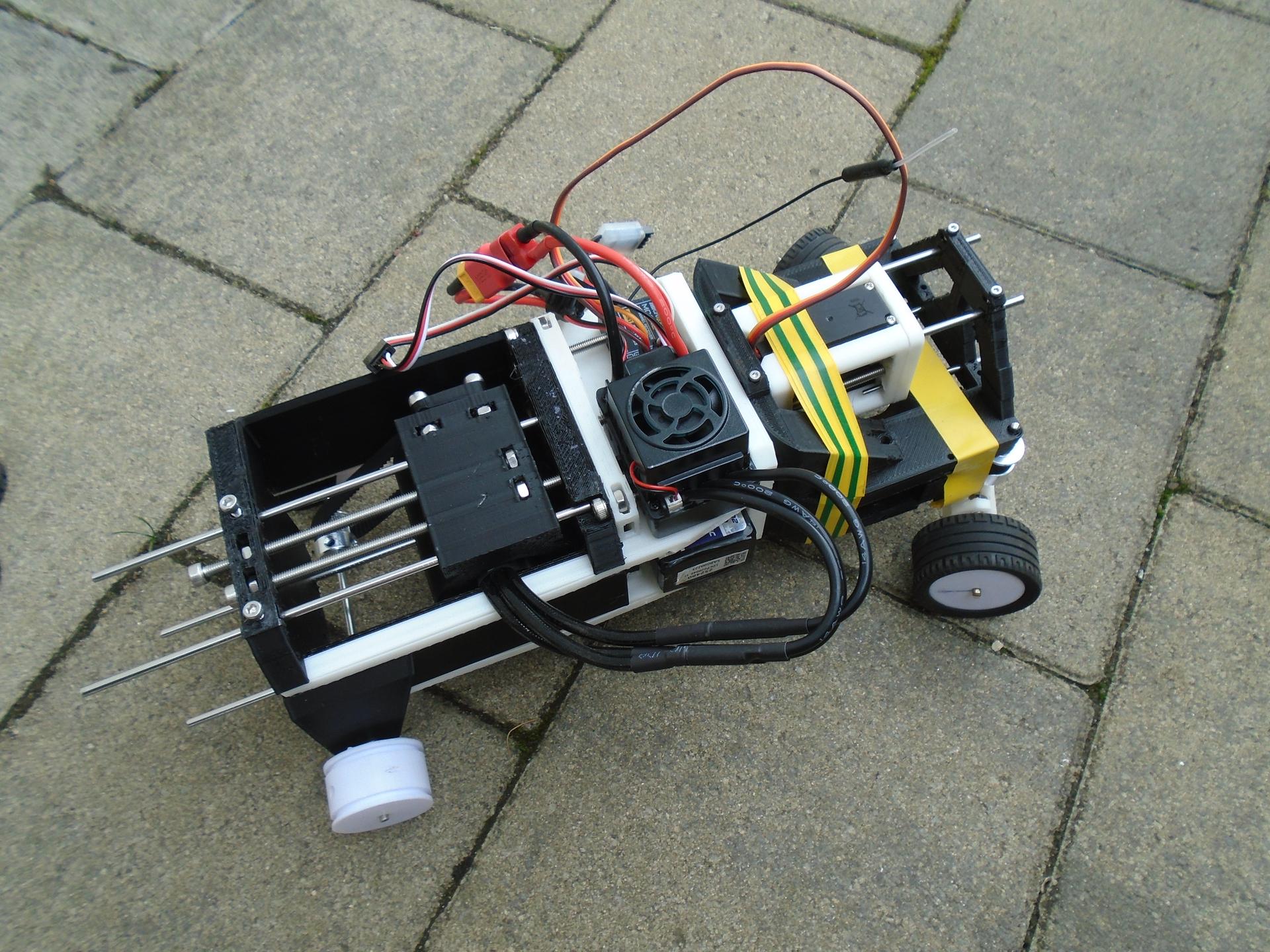
Starting from the front, we have the steering section. This section is actually made of two plates bolted together, with a space between them for a belt to control each wheel. Connected was a sliding carriage that can have it's position set by turning a long bolt. The carriage contained a servo that was also connected to the belt. The idea was too tighten the belt by adjusting the position of the carriage. It was a good idea in theory, however the belts used were just barely too long or too short for the servo to make a taught connection. Another problem was the fact that I used M2 bolts for connecting the two plates together. The printer I was using was simply not calibrated or able to print the parts with the precision needed. Thus the electrical tape shown in the second image. However by far the biggest issue was the connections with the central section.
The central section was a massive success. The compartments fit the components easily, and the screws that affixed them in place worked just as intended. Placing the battery on the bottom shelf was also a good move, keeping the weight low is good for control. However there were problems when it came to interacting with the front. I had designed two systems to attach to the front, one for the upper plate and one for the lower plate. The lower plate had two arms to bolt too, and these were perfect. However for the upper section I was experimenting with 3D printed slots and holes. There were two chunky square pins on the central section that were supposed to slot into two square holes on the front upper plate. However the printer could not meet the needed tolerances to make the parts fit. So I had to saw off the pins and use the tape to attach the plates together. The centre also had a third method of attaching. These were four extremely long pins that slotted into channels in the rear section. However these long pins would be extremely fragile, there was no way 3D printed plastic could hold that force. So, a round hole was printed through the entire pin, allowing for a 3mm axle to perfectly flit through, adding reinforcement. This worked perfectly, and is a major inspiration for the next version.
The rear section was ~rectangular in shape, with a large hollow in the centre where the motor carriage sat on rails, just like the servo. It could move to tighten the belt. This worked perfectly. The attachment to the Central section is secured with larger M3/4 bolts. These were perfect, and the printer handled these tolerances with ease. Next is the carriage. It consists of the motor in a plastic housing and a bolted front plate, with 100mm screws to adjust the cable's tension This worked well, however the power of the motor was a problem. The motor was so powerful, combined with the tension of the cable, the axle melted through the plastic and escaped.
From this iteration, some valuable lessons were learned. The limits of our manufacturing methods were tested and new features added. All these lessons shall be essential for the next version.
New ideas:
- Heavy usage of nuts and bolts
- Several smaller pieces used to assemble into one larger chassis
- Using belts for transmission of motion
- Axle reinforcement
- New more powerful motor
- New reversible ESC
- Structured compartments for each electrical component
- Adaptive cable tensioning system
- Plastic mating structures
- Using washers to distribute the load of bolts
Lessons learned:
- Bolts are amazing. The tolerances of my printer don't allow for much use of the smaller ones, but the larger ones are amazing
- Washers should be used as much possible to reduce damage to the plastic parts
- Plastic mating surfaces / arms with my printer should be avoided, as my printer lacks the precision to make these parts accurately.
- The new motor is so fast (along with the tensioning from the cable) it causes the axle to melt through the plastic. Perhaps some bearings, active cooling, non-thermoforming plastic or grease is needed?
- Related to the previous point, the motor's maximum speed is so fast it throws the tyres off the wheels. Gear ratioing required in order to bring speed down to a manageable level
- Housing for each electrical component is extremely useful as well as keeping the craft stable
- Keeping the weight low helped for balance. The top-heavy design of Snark did cause it to fall over occasionally
Mark IV: Houndeye
Houndeye is still being worked on! Progress is delayed due to my solidworks student licence not covering all of summer. It will have the following features:
- Metal reinforced chassis
- Gear ratioing
- Solidworks assembly
- Stress and impact simulation
- Improved steering system
- Standardised Parts
- Passive cooling system